hra fb twitter
sheffield
header

Frame Assembly Phase 1

First First Previous Previous uparrow Back to Index Next Next Last Last
76 records found. Page 2 of 8 displayed.

For most of the photos on this page, you can click the image for a larger picture.

Highslide JS September 2019


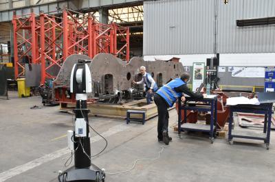
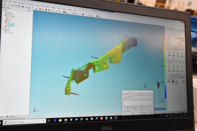
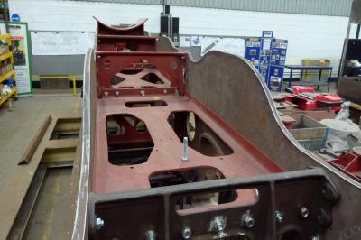
Once all of the frame components had been loosely fastened in place, it was time to check frame alignment. We were fortunate to be supported by Hexagon Metrology whose technologies capture quality data for measurement, positioning and inspection. We needed to make sure that the frames were straight and parallel before proceeding with installing fitted bolts. The laser scanner records the placement of the measuring device in space and that information is transmitted to the PC on the right. By taking lots of measurements, a model is built up of the frames.
Highslide JS September 2019


The model showed that the frames had a bow to the right in the centre - greatly exaggerated on the screen. This was corrected before proceeding.
Highslide JS September 2019


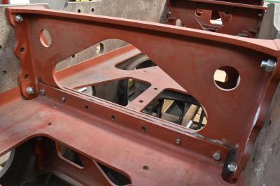
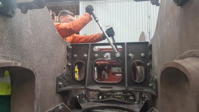
Following the successful alignment check we start the lengthy process of replacing the temporary bolts with fitted, driven bolts. CTL Seal started on the horizontal flanged stretchers. There are 3 of these behind the smokebox saddle and one in front. At this stage, we are only concerned with the 3 behind the smokebox saddle. Each horizontal stretcher requires a "made to fit" packing piece at one end to take up any gaps.

At the rear of stretcher 1 and the front of stretcher 2, both stretchers bolt to a vertical stretcher. Similarly for stretcher 2 rear and stretcher 3 front. As it is impossible to get the magnetic drill in position (as the flanged stretcher gets in the way) it was necessary to remove stretcher one, drill and ream through the vertical stretcher and stretcher 2. Refit stretcher 1 and remove stretcher 2; then drill and ream through the vertical stretcher and stretcher 1. Only then can the fitted bolts be installed.
Highslide JS September 2019

Here is the vertical stretcher and stretcher 1 being reamed out to the correct size.
Highslide JS October 2019


Progress with installing the horizontal flanged stretchers. The rear stretcher is bolted to the brake cylinder support stretcher.
Highslide JS October 2019


Anthony Pilkington from CTL Seal tightens up the fitted bolts on the brake cylinder support stretcher to the correct torque setting.
Highslide JS November 2019


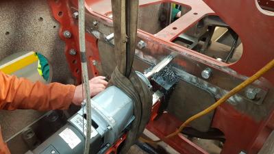
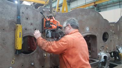
Once the fore and aft bolts on the horizontal stretcher have been installed, it was time to turn to the bolts securing the various stretchers to the frames. The magnetic drill is heavy so it is suspended from the overhead crane. Pete then drills and reams to the final size before driving the bolt.
Highslide JS January 2020


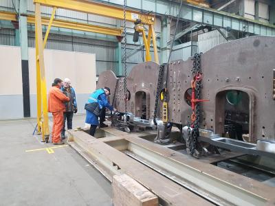
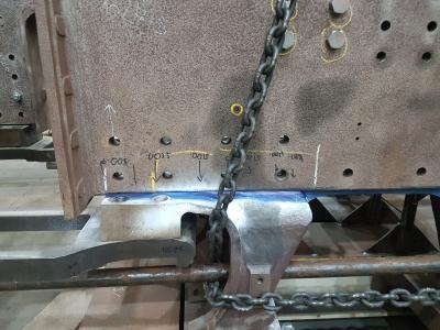
At this stage we became concerned that the frames were not bedded down onto the combined frame stretchers. CTL Seal chained the frames down onto the stretchers. We sought advice from Dave Reynolds from the East Lancashire Railway and John Hind from the Advanced Steam Traction Trust.
Highslide JS January 2020


Careful measurements showed that there were gaps between the stretcher and the frame plates. Therefore the combined frame stretchers were removed so that the face could be machined.
Highslide JS March 2020

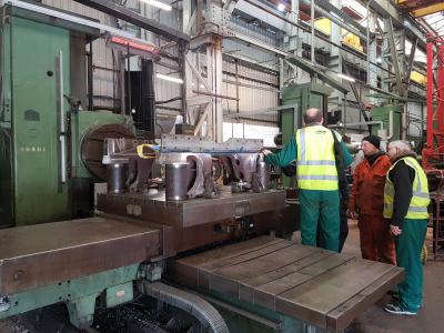
We decided that the combined frame stretchers needed more machining. All of the securing bolts were removed and the frames were lifted off the stretchers. The stretchers were then moved to the machine shop - here we were discussing what was required with CTL Seal.
First First Previous Previous uparrow Back to Index Next Next Last Last
76 records found. Page 2 of 8 displayed.